LLC "GEODIGNOSTIKA"
196233, Russia, St.Petersburg, Vitebsky prospekt, d.109 phone: 89111582796 E-mail: arhipov8@mail.ru Internet (ru): www.geodiagnostics.ru Internet (com): www.geodiagnostics.com
CHECK AND MONITORING OF CONDITION OF CONCRETE SLURRY WALL, JET-GROUTING AND FROZEN SOIL FENCES BY CROSSHOLE SOUNDING METHOD IN UNDERGROUND CONSTRUCTION
Arkhipov Alexey
Doctor of Technical Science, General Director of "Geodiagnostika" LLC, St’ Petersburg, Russia
e-mail: arhipov8@mail.ru
Abstract
"Check and monitoring of condition of concrete slurry wall, jet-grouting and frozen soil fences by crosshole sounding method in underground construction" includes investigation results on the state of massifs of artificial soils established using a set of geophysical acoustic methods. Object of investigation are slurry wall panels, body and joints jet-grouting and frozen soil underground fences. Methods of geophysical investigation are crosshole acoustic and ultrasonic sounding from holes or embedded tubes. For investigation use crosshole sounding apparatus APZ-1 developed by LLC "Geodiagnostika" and ultrasonic device Pulsar 2.2 DBS. The author postulates that non-destructive testing provides the most accurate information about the state of the enclosing structure in the place of manufacture in the underground space.
Keywords
Condition of artificial soil massifs, discontinuity zone of concrete slurry wall, jet-grouting, frozen soil fences, geophysical methods, crosshole sounding
Introduction
The urgency of the problem of control and monitoring of slurry walls, jet grouting and frozen soil fences and grout curtains in the underground space is determined by the requirements of accident-free of tunnel works and the safe operation of buildings after construction. Since 1955 All-Russian Scientific Research Institute of exploration methods (VITR), and then from 2006 LLC "Geodiagnostika" (www.geodiagnostics.ru) investigated the relationship between the parameters of elastic waves and soils and perform tests of continuity in fences in the underground space. Results of the study were the basis of development of new control and monitoring technologies of fences condition by geophysical crosshole sounding method [1].
The aim of research was to obtain the dependencies between the parameters of elastic waves and continuity, strength and elasticity of artificial fencing material. The ultimate aim of research is the creation the table of diagnostic characteristics to determine the condition of the fence by crosshole sounding.
1. Physical background of acoustic crosshole sounding methods for integrity control of artificial soil massifs
Reinforced concrete, jet-grouting and frozen soil structures (slurry wall, fences from bored piles, etc.) are different in their physical and mechanical properties from properties of aqueous soils they are arranged in. Propagation of elastic waves in the concrete, jet-grouting and frozen soil mass is defined by general acoustic rules. A lot of research was carried out earlier proving a correlation between elastic wave parameters and strength and elasticity of materials [2,3,4]. Elastic wave parameters (speed, range and spectrum) depend on properties of the environment they are propagated in.
The speed of elastic wave in linked to concrete, jet-grouting and frozen soil strength. If there is an non-integral area (pores, fracturing) in the path of the elastic wave in the tested object, then an "acoustic shadow" is observed in the form of a sharp decrease of speed, range and frequency of the elastic wave impulse.
The physics of the acoustic shadow phenomenon is based on reflection of the elastic wave on the boundary between the defective area and the soil mass and on the elastic waves rounding (diffraction) of the obstacle with extension of its propagation path. A correlation between the elastic wave speed and strength and porosity of materials and emergence of the acoustic shadow phenomenon in case of defects constitute the physical background for control of concrete, jet-grouting and frozen soil objects quality by means of sounding by elastic waves of different frequency ranges (acoustic 0-20000 Hz, ultrasonic above 20000 Hz). Discontinuity and break zones are marked by lower speed of elastic waves.
When concreting the acoustic (ultrasonic) sounding method is used to define the strength of concrete, such as handling strength, transfer strength, at the intermediate and design age of concrete as defined by norms, technical and design documentation, in the process of concrete maturing, and at the expert control stage. The concrete strength is defined in structures based on experimentally set calibration ratios such as the ultrasound speed/concrete strength. Similar approaches are used for jet grouting and freezing of soils
2. Methodology for crosshole sounding from embedded pipes or holes
Research methods included crosshole sounding, laboratory measurements of elastic speed of waves, compressive strength and modulus of elasticity in jet grouting and concrete core samples and comparison of crosshole sounding results with fence condition after excavating end.
The sounding methodology includes excitement and receipt of an elastic wave impulse in holes (embedded tubes) and assessment of crosshole environment, as a rule, based on parameters of the direct longitudinal wave going through it. The monitoring system is selected on the basis of tasks. A survey layout (plan view) is defined by the client by positioning monitoring tubes or boring holes. Depth survey scheme: simultaneous with moving borehole tools parallel to the ground surface (Fig.1).
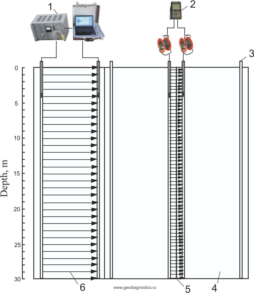
Figure 1. Scheme of crosshole sounding of protection fences and grout curtains
1 - Аcoustic crosshole sounding apparatus APZ-1; 2 - ultrasonic device Pulsar 2.2 DBS; 3 - embedded tubes ; 4 - panel; 5 - joint between the panels; 6 - direction of sounding rays
The depth survey interval is 0 - 100 m. The borehole tools step for descend movement is 0,5 - 1 m. Diagnostic parameters showing the condition of materials are the speed of elastic wave (arrival time), the acoustic pressure range and the elastic wave pulse spectrum. The speed of the longitudinal elastic wave is the key diagnostic parameter. Additional advantages of the crosshole testing method are the following: a possibility to implement crosshole tomography due to the higher number of differently directed rays passing through the crosshole area.
3. Geophysical equipment
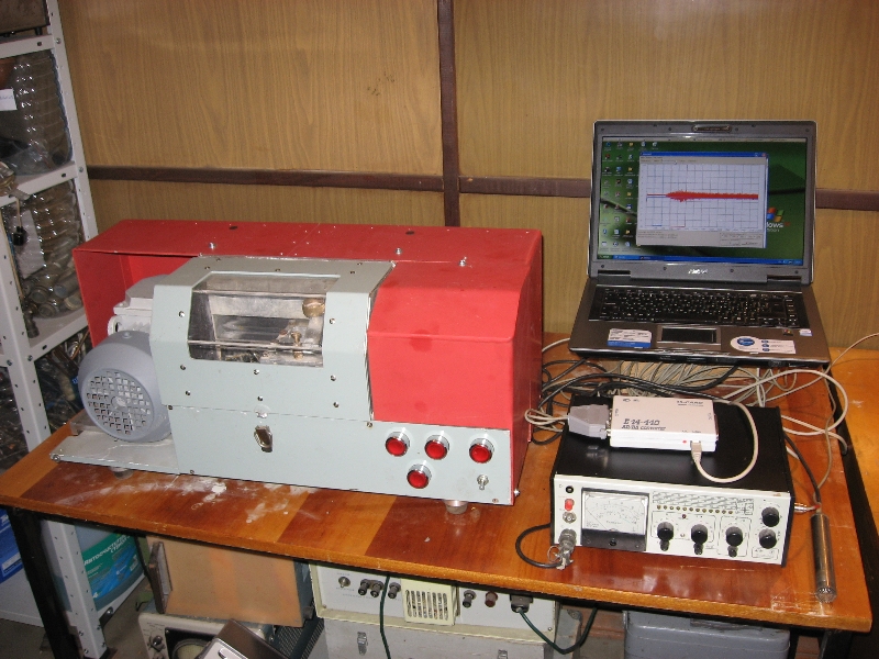
In studies used pulsed acoustic crosshole sounding apparatus APZ-1 (developer "Geodiagnostika", Russia) and ultrasonic device Pulsar 2.2 DBS (developer LLC "Interpribor", Russia).
Operation principle of hardware system is acoustic or ultrasonic waves sending, receiving impulse upon passing through the area (concrete, soil, soil-cement, etc.), registration of impulse on PC hard drive, measuring impulse parameters by the operator, processing the observation results and assessment of the state of propagation area according to impulse parameters.
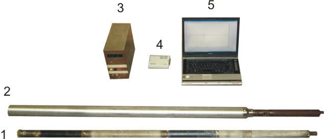
Сrosshole sounding apparatus APZ-1(Fig.2) is designed for measuring propagation time, amplitude and impulse frequency of elastic waves in formations between the source and receiver to determine elasticity characteristics of the area.
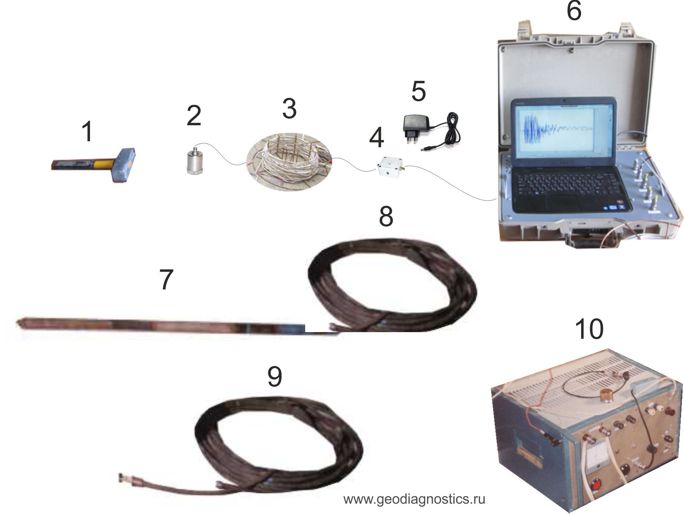
Figure 2. Crosshole sounding apparatus APZ-1
1 - impact hammer; 2 - vibration transducer; 3 - cable; 4 - transitional box; 5 - power supply; 6 - complex of software and hardware; 7 - downhole receiver; 8 - downhole receiver cable; 9 - cable with the electric spark radiator; 10 - current pulse generator
Apparatus APZ-1 consists of sender and software measurement system with the set elastic waves receivers for surface and borehole measurements. Basic technical characteristics of the hardware system are indicated in Table 1. Excitation of elastic wave is carried out by mechanical or electrohydraulic shock. Excitation of elastic wave by mechanical shock is performed by a shock hammer. For excitation of elastic wave impulse, the sender enables the current impulse generator, cable and electric spark source by electrohydraulic shock. The metering system consists of receivers of elastic waves (borehole receiver or vibrator converter), cables and PC based set of hardware and software tools. Borehole devices are operating together with logging hoist equipped with KG-3 cable or directly from the cables at shallow depth. Hardware and software tools is designed for registration, processing and analysis of measured data. Software consists of WINDOWS Operational System, command mode software and WinPOS digital signals processing program. There can be additional software programs for digital processing of these measurements, including tomographic image of cross-hole space, such as TOMOGRAPHIYA (developed by Geodiagnostika LLC) software interface, DOGSTOMO and TOMOSEIS programs.
When carrying out ultrasonic sounding of concrete, as a rule, the impulse repetition rate ranges between 1-50 Hz, the carrier frequency is 20000-100000 Hz, the minimal size of detectable defects is 0.1-0.2 m, the acoustic pressure at the elastic wave impulse front is not big (in Pa). The ultrasonic method has a high resolution but is characterized by a relatively short length of up to 2-3m; it also has limitations for use in highly absorbing mediums. A rational gauge length is 0.2-2 m.
As a rule, during crosshole acoustic testing of concrete the impulse repetition rate ranges between 0.1-0.3 Hz and the carrier frequency between 1-20000 Hz and higher, acoustic pressure at the elastic wave impulse front is high (up to MPa), rational gauge lengths are 0.7-10 m, the minimal size of detectable defects is 0.5 m. The cross-hole testing method has sufficient resolution characterized by a longer length of up to 50 m, and due to the high elastic wave energy it can be used in highly absorbing mediums (sounding through boundaries between mediums)
Distance of sounding in concrete for apparatus APZ-1 is not less than 50 m, for device Pulsar 2.2 DBS - up to 2-3 meters.
4. Research results
4.1. Check and monitoring of fences in the underground space
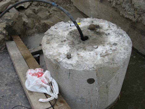
Investigations were carried out on hundreds of concrete slurry walls, jet grouting and ice-soil fences, grout curtain and piles in the construction of the mine shafts (Volkovskaya, Mezdunarodaya, Bucharestskaya and others), tunnel sewers (tunnel of Northern part of the St. Petersburg, tunnel in area Ploshchad Muzhestva and others), Ring Road, Western High-Speed Diameter, Building of the second scene of the Mariinsky Theatre and others.
For the main types of fences and piles the table of diagnostic characteristics are made. Тables of diagnostic characteristics allow to define the condition of the object of research (continuity, heterogeneity, the presence of defects) on the basis of a combination of diagnostic parameters (elastic wave velocity, the acoustic spectrum, the attenuation coefficient). The main diagnostic parameter - the speed of longitudinal elastic wave.
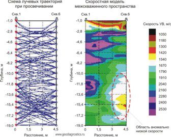
Graphics on speed of elastic wave in the concrete slurry wall - depth relationship at the site of construction of the smoke extraction mine DU2 of the Complex protect St. Petersburg from floods are to be seen on fig. 3. Reducing the speed of elastic wave in concrete occur in areas of divergence of neighboring concrete piles in the intervals of occurrence of the fill-up soil and water-filled sand. Discontinuity zones in the concrete slurry wall have caused the inflow of water into the mine in the process of excavation.
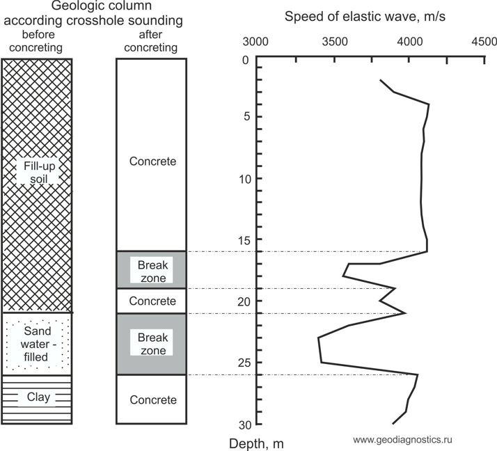
Figure 3. The relationship between the speed of elastic waves and depth after the concreting of diaphragm wall of the smoke extraction mine DU2 at the Complex protect St. Petersburg from floods (2011)
Graphics on speed of elastic wave in jet grouting massif - depth relationship at the site of construction of the building of the second stage of the State Academic Mariinsky Theatre are to be seen on fig. 4. Geological section on the complex seismic acoustic indication was divided by depth into the following intervals: 0 - 8,5 m - modified soil with jet grouting soil; 8,5 - 11,75 m - jet grouting soil with the inclusion of soil; 11,75 - 14,25 m - monolithic jet grouting soil; below 14,25 m - sandy loam. The maximum speed of elastic waves fixed in the interval 11,75 - 14,25 m there was deposition monolithic jet-grouting plate.
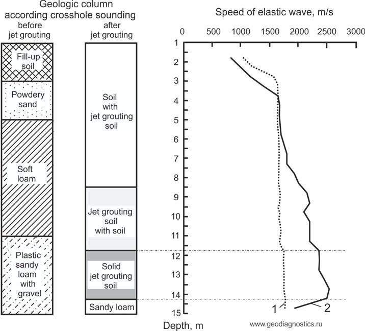
Figure 4. The relationship between the speed of elastic waves and depth before (1) and after (2) jet grouting of soil at the site of construction of the building of the second stage of the State Academic Mariinsky Theatre (2008).
Graphics on speed of elastic wave in the fence from frozen soil - depth relationship at the site of construction of the reception mine for inverted siphon (underground pipeline) to Kronstadt (St. Petersburg) are to be seen on fig. 5.
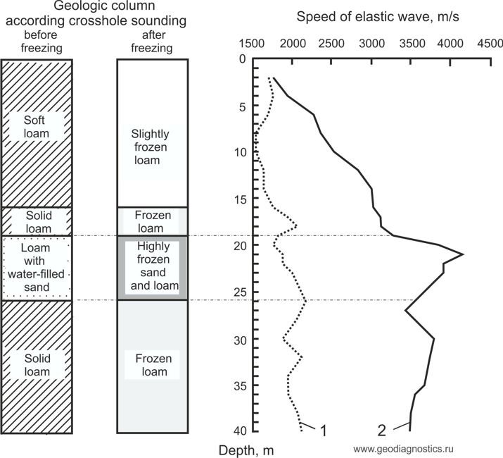
Figure 5. The relationship between the speed of elastic waves and depth before (1) and after (2) freezing of soils at the site of construction of the reception mine for inverted siphon (underground pipeline) to Kronstadt (2010)
The aims of crosshole sounding fence from frozen soil was the allocation of intervals water-filled soil before freezing and determining the degree of soil freezing for the safe excavation. Water-filled soils (sandy loam with interlayers of sand) found at the depth 19-23 m (fig. 4). The range of speed of elastic wave velocity 3812-4182 m/s point to a sufficient degree of freezing of water-filled soils for safe excavation.
4.2 The calibration dependence "speed of elastic wave - compressive strength"
Most known to produce calibration dependence "speed-strength" for concrete. In Russia, the investigation of calibration dependencies for concrete is made on the basis of document GOST 17624-2012 "Ultrasonic method of strength determination".
In my experience, for quality control of jet grouting forming massif the crosshole sounding method more efficiently than core sampling. In St. Petersburg, on large construction sites were conflicts in the assessment of the quality of jet grouting work performed. The reason of conflicts was use the traditional method of rotary core drilling with followed laboratory test of jet-grouting soil cores at uniaxial compression. It does not take into account two factors. First - jet-grouting soil is much less solid and homogeneous compared with concrete. The second - the core sample in single-core barrel are not protected from contact with the rotating and vibrating core tube and subjected to abrasion and crushing. Therefore jet-grouting soil strength determined by the core is much smaller than installed in the project documentation.
During the period 2003-2007 at the construction site of the Ring Road around St. Petersburg, hundreds of jet-grouting cores samples after the measurement of speed of elastic wave were tested for compression. We get a few calibration dependencies with areas of application depending on the type of replaced natural soil. The calibration dependence "speed of elastic wave v - compressive strength R" for jet grouting soil based on loam and sandy loam (is shown in Fig. 6) was approximated by a function of the form:
R = 0,1142 e 0, 0017 v (1)
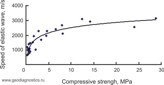
Figure 6. The relationship between the speed of elastic waves and compressive strength for jet grouting soil from the construction site of the Ring Road around St. Petersburg
Dependence (1) has been tested in dozens of construction sites in St. Petersburg
The calibration dependence "speed of elastic wave - compressive strength" allow to control the strength of the material of fences in situ by crosshole sounding and abandon coring.
Conclusion
A result of research made the following conclusions
1. Geophysical method of crosshole sounding between the holes drilled in the artificial soil or between embedded tubes installed in the reinforcement before concreting provides check and monitoring the condition of protection fences and grout curtains during the construction of the underground mines and sewers.
2. Characteristics of crosshole sounding apparatus, including operating frequency range and sound pressure on the front of the elastic wave pulse, selected depending on the elastic properties of the fencing material.
3. Determination of strength jet grouting soil and concrete by crosshole sounding in situ eliminates the need core samples from underground fences.
Aleksey Arkhipov
Doctor of Technical Science, General Director of "Geodiagnostics"
TECHNOLOGIES OF IMPULSIVE ACOUSTIC AND ULTRASONIC CROSSHOLE MEASUREMENTS, RAYING AND PROBING WHEN CONTROLLING CONTINUITY OF UNDEGROUND FENCES, PIT-SHAFT GUARD, ROAD FOUNDATION AND BRIDGE BEARINGS
Acoustic, elastic, deformation, strength properties and fracture porosity of materials of foundations of building and structures (soil, concrete, soil cement) are connected together, that allows to use acoustic methods when controlling quality of constructions, exploration and geotechnical works.
Technical means and technologies of impulse crosswell acoustic raying and probing of rock masses were developed by All-Russian Research and Development Institute of exploration methods in the end of 60s years of 20th century. MAP-1 (1974) and API-1 (1981) equipment were in serial production.
After Institute reorganization works on development of technical means and technologies of acoustic raying and probing were passed to Geodiagnostics Ltd. Currently there is developed computer-controlled hard-ware system of impulsive acoustic raying and probing APZ-1 include: radiation emitter and measuring system. Radiation system consists of current impulse generator, high-voltage cable and electric spark source. Measuring system of borehole receiver or vibration inverter, reinforcing agent and complex of PC-based software hardware. Borehole equipment is used jointly with logging truck hoist equipped by KG-3 type cable in hydro filled boreholes or shot holes with diameter 46 mm or more, depth to 150 mm and in distances between them 100 mm.
APZ-1 hardware system is intended to measure transmission time, amplitude and frequency of elastic waves impulse in rock mass between emitter and receiver with the purpose to determine environment elastic properties. APZ-1 hardware system is calibrated by Research and Development Institute of Metrology after Mendeleev (Certificate of measuring mean calibration № 2520-944 d.d. 11.04.06). Main APZ-1 measure percentage error: time +5%; vibratory acceleration +8%; oscillation frequency +2%.
Hardware system provides:
- monitoring of soil conditions and reconstructions of surface building foundations before and after influence on them by different reinforcement ways; monitoring of quality of soil bondability and cementation in mine roadways construction (holes, tunnels, inclined tunnels) and road foundations;
- determination of pore spaces existence and concrete slabs environment properties; monitoring of conditions tunnel lining and road surface, control of auger and precast piles and bridges concrete bearings;
- geological segmentation, detection and edging of blind ore bodies, quartz reefs, fracture zones, karsts, talik, buried ice, lower bound of incoherent mass and residual soil.
- Translucence distance of incoherent soils (sand, sandy clay) is no less than 20 m, on rocky soils (granites) reaches 150 m. Penetration depth in rocky soils and concrete is to 40 m. Resolution ability in soil acoustic raying is + 0,5 m, in rock mass and concrete raying is + 0,05 m.
Technology of search of ore bodies in crossholes by means acoustic raying is probated in period between 1970-1990 at tens of USSR deposits , including deposits of Kochbulak (Uzbekistan), Uzudmurt (Kazakhstan), Karamken (Russia). Use of acoustic raying provides detection of ore bodies in crossholes and underground space that allows to increase qaulity and correct of evaluation of deposits of mineral resources, decrease expenses at exploration due to decrease of number of exploration bores and excavations.
Technology of exploration of ice soil borders by means acoustic raying is designated for monitoring of ice soil borders before drivage. Main diagnostic characteristics of ice soil borders integrity conditions is speed longitudenal elastic waves in ice soils. Instructional guidelines on monitoring of ice soil borders integrity by crosshole acoustic raying when constructing tunnels in difficult hydro geological conditions published in Leningrad, 1981, are approved by Government of Glavtunnelstroy of USSR. First works on monitoring of ice soil borders were executed in 1974 at Outwash section of Kirovsk-Vyborg line of Leningrad underground (O. Andreev is works head). In 2001-2006 in St.Petersburg there executed integrity monitoring of ice soil borders of 12 separate shafts 214bis (Karbysheva street), 507 (Olhovaya street), 440 (Shamuana street), 17/2 (Konyushenny per) and others that provided accident-free shaft sinking.
Technology of investigation of soil cement borders by acoustic raying is intended for control of soil cement borders integrity made by method of jet cementation before drivage and construction. Main diagnostic character of soil cement borders integrity is speed longitudenal elastic waves of soil cement. In 2001-2006 in St. Petersburg there executed integrity monitoring of soil cement borders
of shafts 4 (Grazhdansky pr.) and 1 (Kushelevka) of relief sewer on Ploschad Muzhestva area, rig road tunnel in joint of Toksovskaya street (Murino), cells of 1 and 2 sections of construction of second stage of Mariinsky Theatre, troughing part of T4-C complex of St.Petersburg protective structures from inundations etc. ion the basis of data of acoustic raying of shafts 4 (Grazhdansky pr.) there was made a decision to conduct additional injection that would provide zone closing of discontinuity flow, and, finally, accident-freee shaft sinking.
Technology of investigation of auger piles and precast piles and bridges concrete by acoustic raying is intended for monitoring of pile properties: integrity, length, form, concrete strength class. Method essence is mechanical excitement of pile head by results of comparison of properties and echo-signal in constructional of diagnostic characteristics of piles different conditions. The technology was probated in 2002 in construction of laboratory building of St. Petersburg State Mining University (Nalichnaya street), bridges bearings, pile foundations of highways on ring road and West Speed Diameter.
Technology of investigation of soil cement piles of road foundations by acoustic raying and logging is intended for bearing properties monitoring: soil concrete integrity, length, diameter, strength. Methods essence if excitement of impulse of acoustic waves after pass in soil concrete and bearing state assessment on results of comparison of acoustic waves impulse with the table of diagnostic properties of bearing states. Soil concrete strength monitoring is executed on the basis of dependence acoustic waves - strength in linear compression. In 2004-2006 the technology was widely used in construction of road ring around St. Petersburg in sections LOT1 and LOT6.
Technology of investigation of condition of mining liner by probing is intended for monitoring liner condition and holes search under concrete slabs. Methods essence is point mechanical impulse excitement of surface of mining lining and defining of its condition by time, magnitude and frequency and phase properties of acoustic echo-signal. Technology was applied in 2003 in investigation of lining of tunnels 1 and 2 (Outwash section) between Lesnaya and Ploschad Muzhestva stations of St. Petersburg underground with the purpose to determine depth of protective reinforcing matrix layer and holes existence in tubed space.
Aleksey Arkhipov
Doctor of Technical Science, General Director of "Geodiagnostics"
196233, St’ Petersburg, Vitebskiy, 109
phone: 89111582796
Fax: (812) 727-45-91
E-mail: arhipov8@mail.ru
Internet (ru): www.geodiagnostics.ru
Internet (com): www.geodiagnostics.com